
Today, anyone who sits down in an airplane, car or other means of transportation, or uses an elevator, expects flawlessly functioning technology. Every day, our lives depend several times on the safe functioning of the mechanized and automated world that surrounds us. Often, we do not even think about a possible risk, but trust completely the responsible designers and manufacturers of the respective products, according to the motto "they surely know what they are doing"!
This trust is well justified, because vital parts, which are declared to be safety parts, have to pass extensive tests before they take over the safety for human lives according to their function. For such tests, which have become indispensable in the field of nuclear power plants, for example, different test methods are used today, depending on the problem, which together belong to the group of "non-destructive testing".
Magnetic particle testing is of particular interest in this context. It can be used to detect gap-like material separations such as cracks in magnetizable material. A crack, no matter how fine, in a highly stressed component can easily lead to fatigue failure and thus become the cause of a disaster.
The following article aims to illustrate the processes involved in magnetic particle testing to the reader in simple terms and illustrations and to provide information on the most important physical principles. The text has been deliberately kept simple, because it is intended to reach readers who have no knowledge in this field. For the specialist, too, this explanation is sure to provide an interesting source of information.
Magnetism AND ITS APPLICATION IN MAGNETIC PARTICLE TESTING
As the term "magnetic particle testing" already makes clear, this method exploits magnetism, i.e. the workpieces to be tested, or generally speaking, the test sections concerned, are magnetized. With small permanent magnets, it is easy to determine that there are materials that are attracted by such a magnet, while others experience no force at all. This results in a distinction between magnetizable and non-magnetizable materials. From this it can already be deduced that not all materials can be detected with magnetic particle testing, but only those which are magnetizable, so-called "ferromagnetic materials" (ferromagnetic = magnetic like iron).
Ferromagnetic materials
For easier understanding, one imagines the ferromagnetic materials as a composition of tiny bar magnets, the so-called "molecular magnets". The commonly known bar magnets always have a north and a south pole at their two ends. If you cut such a bar magnet in the middle, you will get two complete smaller bar magnets with the two mentioned poles.

Again, these newly obtained bar magnets can be divided into two complete magnets each. Mentally, one can continue this game until the size range of the molecular magnets is reached.

Many of these molecular magnets joined together in a disordered direction form the ferromagnetic material, which is outwardly magnetically neutral.

If a strong external magnetic field is now generated, the molecular magnets orient themselves in a common preferred direction corresponding to the external field, after which the magnetic forces of all of them act together and thus become measurable. Consequently, the material is now magnetized. From a physical point of view, molecular magnets are crystalline regions of the material with the same magnetic moment (spin direction of the electrons) of the individual atoms.
Magnetization
Now the essential question arises: How to generate an external magnetic field to achieve the effect of magnetization described above (alignment of molecular magnets)?

The basic answer to this question was given by the physicist Oersted, who first discovered in 1820 that every current-carrying conductor is surrounded by a magnetic field. This circular field can be demonstrated by a simple experiment: For example, you put a copper rod through a piece of cardboard and sprinkle fine iron powder on it. If current flows through the copper rod, all the powder particles arrange themselves in concentric rings, or lines, around the conductor through which the current flows. The lines that appear here represent the course of the field and are generally referred to as lines of force or field lines, which always have a self-contained course.
THEOREM 1
Each current-carrying conductor is surrounded by circular field lines.
If a compass needle is held in this field line region ( fig. 2) and direct current flows through the copper rod, the needle will always align itself tangentially to the circular lines. Very important here is the fact that when the direction of the current is reversed, the compass needle also changes direction by rotating 180°. From this it can be seen that the field lines can be assigned a direction which depends on the direction of the current generating them.
To make this assignment easier to remember, the "right-hand rule" was defined in which, after forming a fist with the thumb spread out, the individual fingers indicate the direction assignment: If the thumb points in the direction of the current flow, the remaining fingers point in the direction of the field lines.
THEOREM 2
The direction of the field lines depends on the direction of the current causing them!

If one now forms a conductor loop from the straight conductor considered so far and repeats the experiment with cardboard and iron powder with it, one recognizes that at both points, where the conductor loop is led through the cardboard, the known circular lines exist ( fig. 3.1).
With the knowledge of the directional assignment it becomes provable that in the area between the two points the field lines have a common direction.

his is also the case in a coil, which in principle consists of several interconnected conductor loops. This means, however, that inside such a coil the field lines of all individual windings have a common direction, which leads to the generation of a magnetic field in the longitudinal direction of the coil (fig. 3.2).
The two ends of the coil behave like the poles of a dust magnet. If there is now ferromagnetic material inside the coil, the field lines run for the most part in this material, whereby they are correspondingly crowded together. The line density (number of field lines per unit area) is therefore much lower in air than in ferromagnetic material. It depends on the "magnetic resistance" of a material, which is inversely proportional to its permeability. Permeability is thus a measure of the penetrability of a material for field lines.
For calculations, the relative permeability is usually used, which links the absolute permeability with that of the vacuum. However, this "permeability" of a material not only depends on the composition of the material, but also changes with different degrees of magnetization. It is very high for ferromagnetic materials, compared to air or non-magnetizable materials.
THEOREM 3
Ferromagnetic materials have a magnetic resistance 100 to 1000 times smaller than that of air or non-magnetizable materials!
In simple terms, it can be assumed that the field lines seek the path of least resistance, thus running in ferromagnetic material if possible.

This can be demonstrated, among other things, on a closed iron ring to which a coil has been applied (fig. 4). Despite the very asymmetrical coil arrangement, most of the field lines generated by the coil run in the iron ring. If this closed path is interrupted in ferromagnetic material, the field lines must bridge part of this path in air. At this point of separation, a strong stray field is created, which means that the field lines exit the ferromagnetic material on one side of the defect and re-enter on the other side. However, this means the formation of magnetic poles.
Basic principle of magnetic particle testing
If fine iron powder is now scattered over this area of the ring, it will accumulate at the defective spot, because it is attracted by these magnetic poles, i.e. by the scattered field. The field lines again find a way through the powder particles through ferromagnetic material and hold the powder particles at this place.
Since the field line path in the rest of the iron ring is undisturbed, therefore, when the entire ring is sprinkled with iron powder, a powder accumulation remains only at the defective point with the existing stray field. Since the area of the scattering field is considerably wider than the defect, such a "powder bead" can be easily perceived.
This phenomenon already represents the basic principle of magnetic powder testing: If the course of magnetic field lines in ferromagnetic material is disturbed, a stray field is produced, which can be detected with the aid of iron powder. This is also successful in the case of defects with a very small width, which means that even the finest material separations, such as cracks or similar, can be detected.
THEOREM 4
If the course of magnetic field lines in ferromagnetic material is disturbed, a stray field is generated at the point of disturbance!
It is of crucial importance, therefore, that a defect actually means a disturbance for the magnetic field lines.

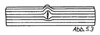
Figs. 5.1 to 5.3 show three principal possibilities of a defect. As in the previous example with the iron ring, in fig. 5.1 the defect is at right angles to the field line direction and thus causes a stray field. Thus, after application of iron powder, this defect could be detected.

However, if the field line direction has the same orientation as the defect (fig. 5.2), this results in only a very insignificant influence on the field lines, which does not cause a stray field. A defect of this type cannot be detected. In the case of defects which are now below the surface, such a clear decision is not possible, because in this case further factors have to be taken into account.
Basically, however, it can be seen that the field line direction and the fault direction must be transverse to each other in order to generate a stray field. The angle between the two directions should ideally be 90 degrees, although angular positions of up to a minimum of 30 degrees are also sufficient.
THEOREM 5
Field line direction and fault direction must be transverse to each other!
If, as is very often the case, the fault position is unknown, magnetization must be carried out in different directions.

If the two directions of magnetization are approximately 90 degrees to each other in this case, all defect directions can be detected because one of the two fields is guaranteed to be in the appropriate angular range to the defect direction.
The above-described regularity sometimes seems to be refuted in practice, because defects are suddenly detected which have the same direction as the magnetic field lines. In this case, the material is usually coarse-grained and cracked along the grain boundaries (intergranular crack). This defect in turn has a lot of transverse components to the field direction, resulting in a stray field (fig. 6.1).
 However, not only the defect direction, but also the defect geometry is an essential factor in the formation of a stray field. Fig. 6.2 shows how the intensity of the stray field increases with increasing "slenderness" of the defect. Thus, the ratio of defect depth to defect width is also important, and for sufficient results this ratio should be > 5.
Magnetization methods
In order to achieve, as mentioned, different field line directions during magnetization, different magnetization methods are available, which are specified by different device types.
Particularly in stationary systems, two or more such systems are sometimes combined with each other to enable fast and thus rational crack detection. However, when several systems are used simultaneously, the physical laws that make this possible must be observed. However, this is the responsibility of the manufacturer, who designs equipment and systems accordingly.
The magnetization methods usually used are listed in the standard "DIN 54 130" and are divided as follows:
| Current flooding |  |
|---|---|
 |
|
| Yoke magnetization (by means of permanent or electromagnet) |
 |
| Magnetization with current carrying conductor |  |
 "Auxiliary flooding" by means of mandrel "Auxiliary flooding" by means of mandrel |
Basic ideads about magnetic particle testing as PDF document (6.2 MB).